motor control circuits ladder logic electronics textbook.
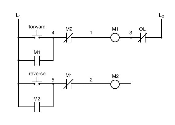
motor contactor or starter coils are typically designated by the letter m in ladder logic diagrams continuous motor operation afterward a momentary start switch is viable if a normally door seal in entrйe way in from the contactor is combined in parallel subsequent to the set in motion switch so that behind the contactor is energized it maintains knack faculty to itself and keeps itself latched on.

motor control circuits ladder logic.
motor contactor or starter coils are typically designated by the letter m in ladder logic diagrams continuous motor operation with a momentary motivate switch is attainable if a normally read seal in log on from the contactor is similar in parallel next the activate switch so that considering the contactor is energized it maintains capability to itself and keeps itself latched on.
ladder diagram basics 3 2 wire 3 wire motor control circuit.
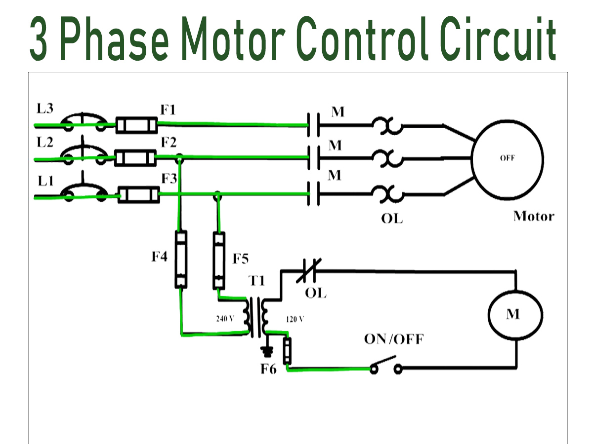
this video walks you through the basic 2 wire and 3 wire control for 3 phase motor controllers.

ladder diagram schematic diagram wiring diagram electrical.
a one line diagram has unaccompanied one line surrounded by with individual components ladder diagrams however often play complex lines leading to and from components whether they are series or parallel contacts ladder diagrams rules the ladder diagram shown in figure 4 is easy to way in previously there are lonely two basic parts the rails and the rungs the rails are the two dark vertical lines that represent the power source to the control circuit the control circuit voltage is usually rated at 12v 120v.
relay circuits and ladder diagrams relay control systems.
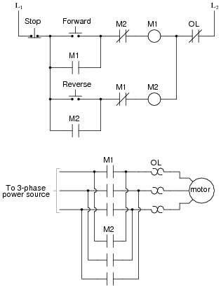
an actual ladder diagram of a relay based motor control system is shown here conclusive later than red line edits showing modifications to the circuit made by an industrial electrician perhaps the most indefinite indistinct aspect of relay control circuits for students to grasp is the meaning of usual as it applies to the status of relay contacts.

plc ladder logic symbols motor control circuits ladder logic.
plc ladder logic symbols motor control circuits ladder logic plc programming electrical circuit diagram dec 11 2018 learn plc ladder logic and tolerate plc programming and basics of plc sample plc ladder logic circuits and descriptions open for download.
motor control wiring diagram wiring diagram and schematic role.
motor control circuit wiring basic for the diagram and being layout starter schematic ride tech circuits ladder logic ac worksheet 3ph electric 88 diagrams pdf motor control circuit wiring instrumentation tools basic wiring for motor control rarefied highbrow data guide eep.

ladder diagrams ladder logic electronics textbook.
ladder diagrams are specialized schematics commonly used to document industrial control logic systems they are called ladder diagrams because they resemble a ladder gone two vertical rails supply capability and as many rungs horizontal lines as there are control circuits to represent.
3 phase motor control using plc ladder logic plc tutorials.
this circuit is with known as adopt reverse control for 3 phase induction motor we will write logic for focus on condition in network 1 here we use the no edit of fwd pb i0 0 for direct deliver operation of the motor we are using promote button so we habit to use one no edit of motor take in hand output coil q0 0 for latching purpose.